3D Print a Modular Librem 11 Back Cover
Latest posts by Jonathon Hall (see all)
- PureOS Crimson Development Report: November 2024 - December 16, 2024
- Purism’s PureBoot is Not Affected by UEFI Key Leaks (Again) - July 29, 2024
- From the Hackdesk: Librem 16 - May 30, 2024
Take Control
Purism makes products that put you, the customer, in control. Generally, Librem devices are easy to disassemble for access to their internals. For the Librem 11, our focus in the first iteration is on the interior components rather than the chassis itself, which means it has an adhesive back.
If you or a friend have a 3D printer, it’s possible to replace that single adhesive component with a modular back cover and screws. With this change, you can disassemble the Librem 11 easily, and it is still only about 8 mm thick.
Materials
You need the following:
- A Librem 11 tablet
- A 3D printer, with print volume approximately 270x170x1.5 mm
- 16x M1.4 screws, 4mm long
- Foil tape, such as for sealing ductwork from a hardware store
- Models for the part – STL files from the linked Git repository
Let’s Do This
First, remove the adhesive back from the Librem 11.
Pry off the “OLED Inside” label with a thin spatula, such as one for your 3D printer (but avoid sharp scrapers). It’s separate from the gray back, so start from the outside edge and it should pop off easily.
Then, peel off the gray back. There is no going back once you remove this – the aluminum in the back will be deformed, and it will not smooth out again.
Start by lifting the edge around the “OLED Inside” label with the thin spatula. There aren’t any exposed sensitive components at the edge, so don’t worry about poking the spatula under the back a few millimeters, just be gentle.
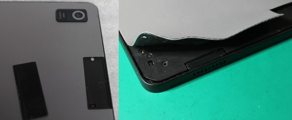
Then, gently peel it the rest of the way with your hands. It should come off without too much force. Do not use the spatula here to avoid damaging the battery or the dock connector ribbon cable. Be mindful of the dock connector ribbon cable while peeling; it crosses the center of the battery. The copper foil should keep it from peeling up with the back.
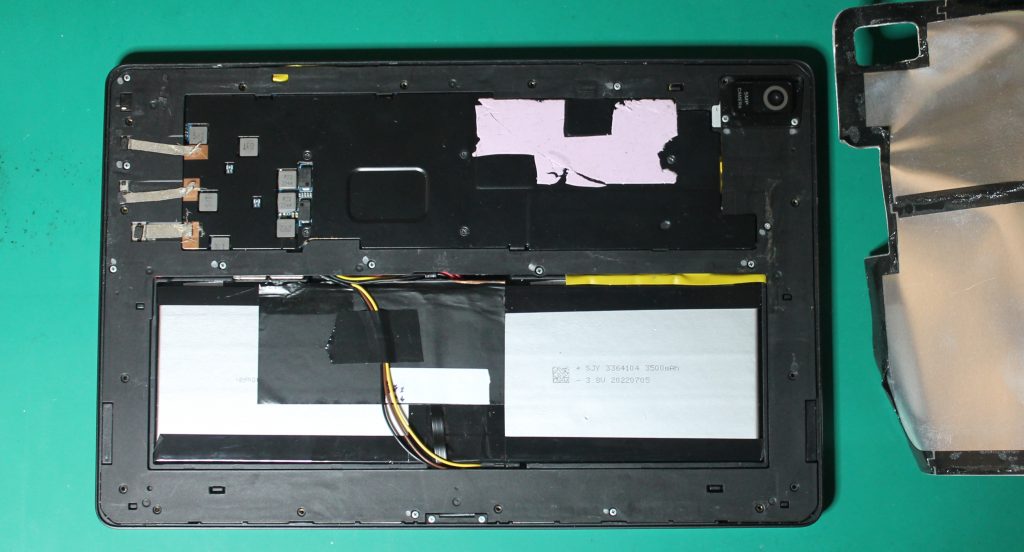
Now you can see the heat spreader, battery, and dock connector ribbon cable. (It will look a little different from mine. I’ve already cut the copper foil and added a UART for firmware hacking, more on those later.)
Test and Check
The model must very precisely match the tablet, so print the test piece first to check. I calibrated it with my 3D printer, but yours might vary slightly.
Load up l11_back_test.stl in your slicer of choice, and apply some settings:
- Layer height: 0.2mm or less
- Perimeters: 1 (important so screw holes are bonded well)
- Infill: 100%, rectilinear, 45 degree fill angle (important so perimeters are bonded well)
Optionally, use l11_back_fill_90_modifier.stl as a modifier for the top layer if you want a different fill angle for looks. I like it with 90 degrees on the top layer. If you do a Hilbert curve, please share pictures!
Print the test piece:
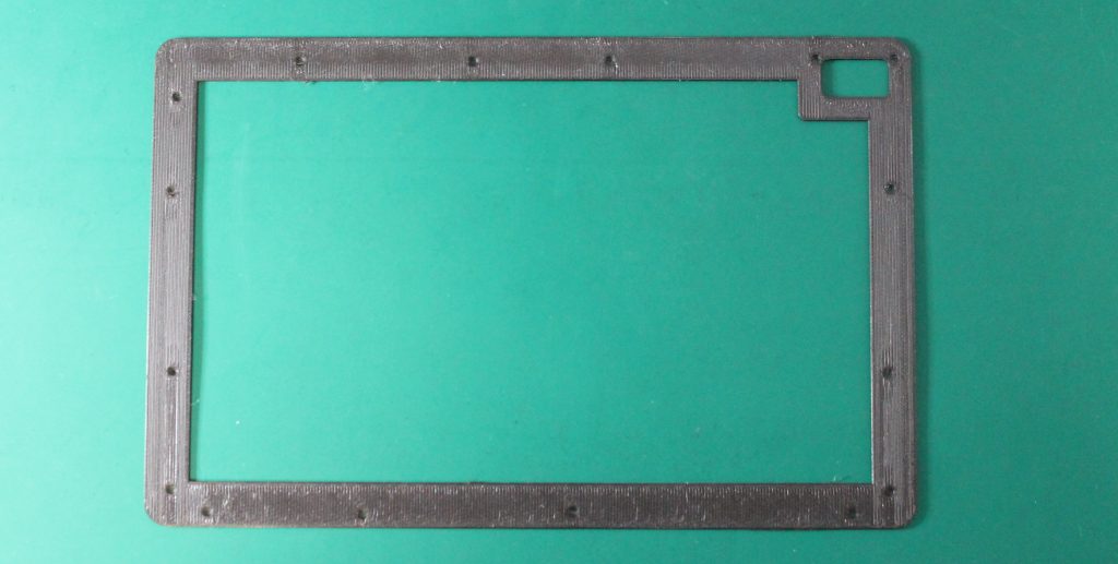
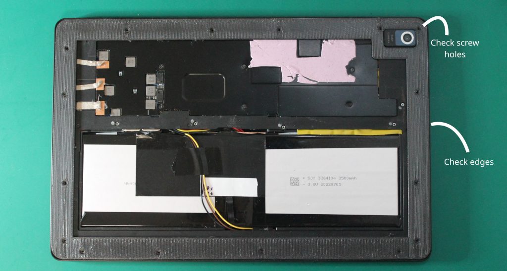
Place the test piece on your Librem 11 and snap the camera corner around the camera lens. If it does not fit well, check for burrs or elephant-foot enlargement on the bottom layers, trim them with a hobby knife.
With that corner down, the other edges should naturally rest inside the lip edge of the Librem 11. If they sit on top, the keyboard cover will not dock. If you have to press them in slightly, it may cause a slight bulge on the real part. Verify that the screw holes all align.
Remove the factory screws that line up with the screw holes on the test piece. We will replace these with 4mm screws. Several of the factory screws will remain to hold the midframe, I marked those with a silver marker.
Screw down the test piece with 4mm M1.4 screws. Tighten well, but do not overtighten. The screws should go in easily without needing to flex the test piece.
If the test piece didn’t quite fit any of the above, adjust the scale and try again. It probably will not need more than 1% adjustment at most. Even 0.2% can make a big difference for this part. (I scaled my original measurements by 100.55% for a precise fit, this is included in the model.)
Print and Shield
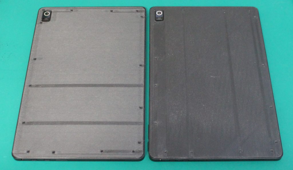
Once you have the scale just right, print l11_back.stl with the same settings.
Apply foil tape to the inside. A little overlap between pieces of tape is OK. Trim the tape with a hobby knife just inside the edge and around the camera hole. Poke out the screw holes with a small screwdriver. Make sure the foil bits don’t end up on the tablet.
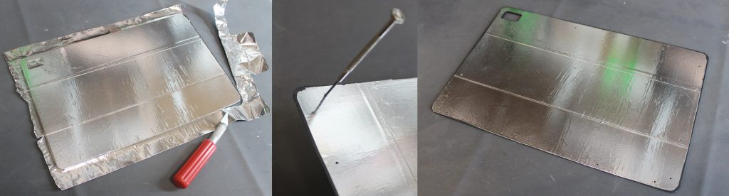
Screw down the finished back with 4mm M1.4 screws.
A Look Inside
Now you can disassemble and reassemble whenever you want!
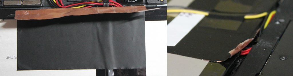
The copper foil attaches the midframe to the battery and heat spreader. Be mindful of the thin ribbon cable running under it to the dock connector. You can peel the top back from the heat spreader and midframe, then cut it there (be extra mindful of the battery wiring and dock ribbon when cutting). You can also peel it off entirely, separating it carefully from the dock ribbon, but I ended up taping the dock ribbon down again anyway.
Remove the remaining 3mm silver screws to release the midframe and camera cover.
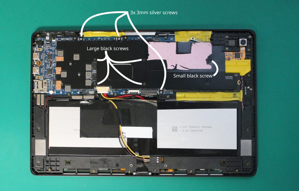
Remove 8 screws from the heat spreader to access the NVMe SSD and mainboard. They are not all the same:
- 3x 3mm silver screws around the edge (a fourth holds only the mainboard)
- 1x small black screw near the SSD, possibly under the thermal pad
- 4x larger black screws around the SoC (CPU)
The SSD is socketed and supports PCIe 1x. SATA SSDs require a firmware modification.
I’ve taped the magnets down on mine, I open it a lot and they sometimes jump out. You can place them on the corresponding spot on the keyboard cover to find the correct orientation.
If you’re a firmware developer, you can externally flash the SPI BIOS flash with the usual SOIC-8 chip clip and programmer.
If you are a firmware or kernel developer, it’s possible to access a UART with soldering. A UART is incredibly helpful for troubleshooting unbootable development builds. It’s even possible to store a 3-pin connector just below the battery, so the back will still go on.
Purism devices are built for your control. Personalize your Librem 11 and show it off!
Purism Products and Availability Chart
| Model | Status | Lead Time | ||
|---|---|---|---|---|
 | Librem Key (Made in USA) | In Stock ($59+) | 10 business days | |
 | Liberty Phone (Made in USA Electronics) | Available on backorder ($1,999+) 4GB/128GB | n/a | |
| Librem 5 | In Stock ($799+) 3GB/32GB | 10 business days | |
 | Librem 11 | Out of stock | New Version in Development | |
 | Librem 14 | Out of stock | New Version in Development | |
 | Librem Mini | Out of stock | New Version in Development | |
 | Librem Server | In Stock ($2,999+) | 45 business days | |
 | Librem PQC Encryptor | Available Now, contact sales@puri.sm | 90 business days | |
 | Librem PQC Comms Server | Available Now, contact sales@puri.sm | 90 business days |
Recent Posts
Related Content
- Privacy Under Siege: Why Purism’s User Sovereignty Model is the Way Forward
- Code is Power!
- Dialing Back to Move Forward: Why the Landline Revival Signals a Future for Privacy
- Google’s New Sideloading Restrictions: Why Purism Thinks Differently
- Introducing the Librem PQC Comms Server