Librem 11 Memory Adventures
Latest posts by Jonathon Hall (see all)
- PureOS Crimson Development Report: November 2024 - December 16, 2024
- Purism’s PureBoot is Not Affected by UEFI Key Leaks (Again) - July 29, 2024
- From the Hackdesk: Librem 16 - May 30, 2024
A Recent Memory
When I started porting coreboot to the Librem 11, one of the first few tasks was to get memory working.
Like the Librem 5, the Librem 11 has soldered memory (“memory down”). This has implications on the firmware. Socketed memory carries a small SPD EEPROM with information about the memory module. Memory down boards don’t have that SPD EEPROM – since the memory can’t change, we just include all that information in the system firmware and save the cost of one more chip.
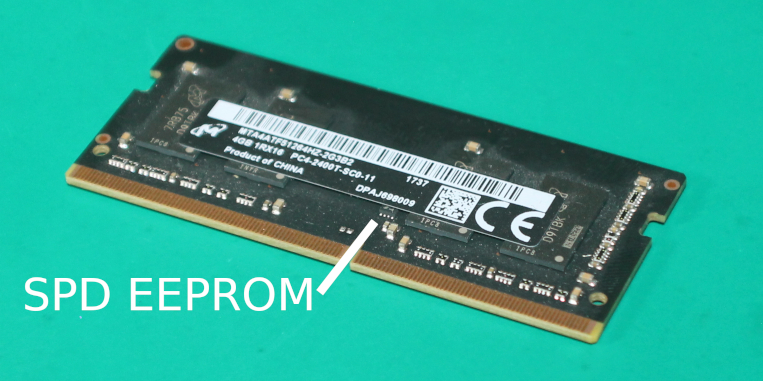
The firmware needs to know things like:
- The memory’s organization, speed, timings, etc. This might be available in a datasheet for the memory part.
- The populated channels. A schematic may tell you this, or you might be able to deduce it from the number of memory parts on the board.
- The DQ and DQS signal routing from the chipset to the memory parts. Since there are so many of these signals, you can mix them up if it simplifies the board layout, but you have to tell the firmware how they are connected. A schematic might not tell you this, because they’ll change in layout – you’d need the actual layout files the board.
These can all be found somewhere. But there is one thing that already knows all of them – the proprietary vendor firmware.
Static Analysis: Dead-End
The proprietary firmware must know all of this, since it’s able to boot the system. How can we get the information out of it?
First, I tried using spdtool, a coreboot tool that looks for patterns of bytes that could be SPD data. I hacked it a little for LPDDR4x, extracted all parts of the firmware with UEFIExtract, and set it to work scanning all of them.
It found a few matches, but none were correct. The firmware must have been constructing this at runtime. Perhaps it stored some of it separately and filled in the SPD at runtime, or perhaps it was just compressed in some way I could not easily find. This was a dead end.
I also looked for the DQ/DQS maps – the mapping of those signals between the chipset and memory parts. This is given to the Intel Firmware Support Package in a specific structure, and there’s an obvious copy of that structure in the firmware image. But it’s wrong – it’s just a bunch of defaults, the firmware must be filling it in at runtime.
A New Approach
Static analysis was no help. I fell back to what I knew to be true:
- The UEFI firmware uses Intel’s Firmware Support Package to initialize memory, like coreboot. The FSP is visible in UEFITool.
- The memory configuration structure for FSP must exist at some point. Intel’s FSP requires that structure.
- If I could capture that structure from the running system, it would contain everything I needed and much more.
If I could replace a bit of code in the firmware at the right time, I could get the configuration. I just needed to figure out where to put the code, and where to send the configuration.
Listening In
I decided to get output via POST codes. A POST code is a debugging tool for firmware. Write one number to the right place, and it’ll appear somewhere, like a numeric display on the board or a “POST card”. It’s not much output, but it’s enough. This doesn’t require any configuration in firmware, so I could do this without knowing anything about what the firmware was doing in hardware.
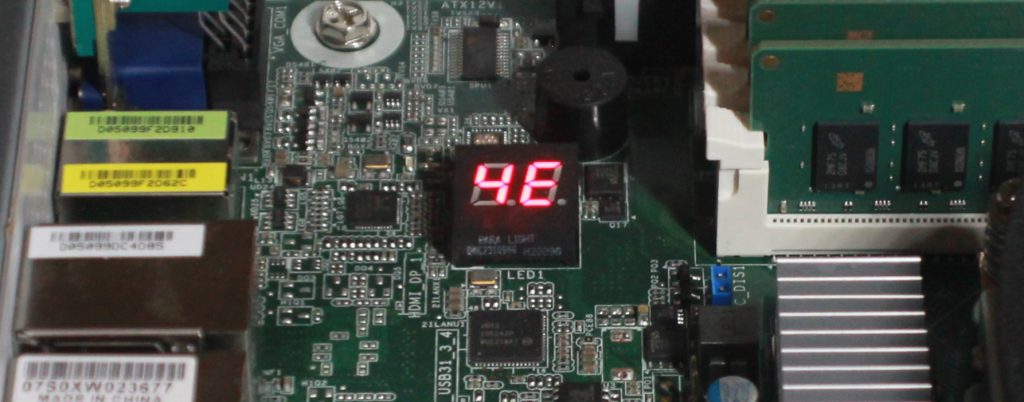
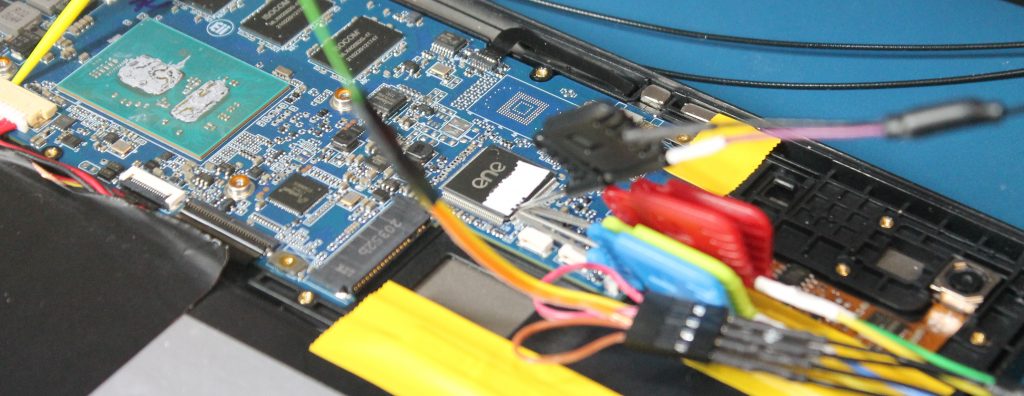
Librem L1UM v2 has a POST display, but of course a compact device like the Librem 11 doesn’t. I attached my logic analyzer to the board, and used it to trace this bus. POST codes appear here, so I could write as many as I want and get a log from the logic analyzer.
UEFI Dispatching
Then, I needed to insert some code in the right place. This doesn’t require any reverse engineering, but it does require traversing hundreds of pages of documentation. Between the UEFI and FSP documentation, we can find the entry point that will execute at the right time.
UEFI firmware doesn’t work the same way that coreboot does. In coreboot, the FSP entry points are just called as functions, mostly like an ordinary C function call.
UEFI is designed to integrate proprietary code from multiple vendors, so it is much more complex. Parts of the firmware provide “modules” that each have a “dependency expression” on the pieces of data they need. Other parts of the firmware publish those pieces of data. When a module’s dependencies are satisfied, it is executed. You can also install hooks to be notified when pieces of data are provided.
In this case, FSP provides a module called FspInitPreMem with some dependencies. That module publishes “default” memory configuration data – the structure with default values filled in. Then, something from the firmware vendor that depends on the defaults executes. It copies the defaults, fills in what it knows about the board, and then publishes that as the “memory policy”. FSP has by this point asked for a notification when the memory policy is published. When it is, FSP will initialize memory.
Taking Over
I don’t care about continuing to boot after I get the information I need, so I replaced FspInitPreMem entirely. The entry point is specified in the executable section’s header, so we can assemble some new code and overwrite it there.
After many, many iterations of spitting out a little bit more data at a time, I got it to add its own notify callback for the memory configuration and write out the relevant data. There were more stumbling blocks along the way, like zeroing out the executable’s relocations, because the firmware still tried to relocate it at runtime.
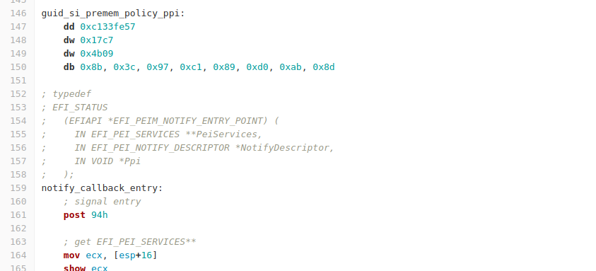
The result was a logic analyzer trace showing everything that went over the bus. With a few regular expressions and spreadsheets, I digested it into a hex dump of the structure:
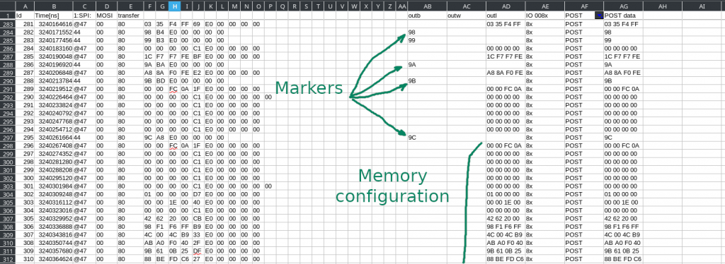
Success!
The memory configuration structure was full of useful information – SPD data, DQ/DQS maps, and much, much more. With the memory initialization now working, the next few pieces came quickly. Soon, coreboot booted on the Librem 11 for the first time to display the coreinfo payload:
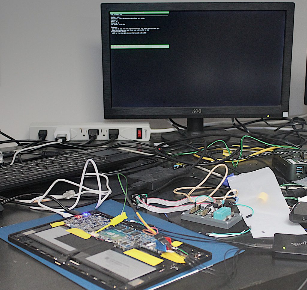
Purism frees you from proprietary firmware. The information needed to boot Librem 11 is now plainly visible in our open-source firmware, and it will be upstream in coreboot soon.
Purism Products and Availability Chart
| Model | Status | Lead Time | ||
|---|---|---|---|---|
 | Librem Key (Made in USA) | In Stock ($59+) | 10 business days | |
 | Liberty Phone (Made in USA Electronics) | In Stock ($1,999+) 4GB/128GB | 10 business days | |
 | Librem 5 | In Stock ($799+) 3GB/32GB | 10 business days | |
 | Librem 11 | In Stock ($999+) 8GB/1TB | 6+ weeks | |
 | Librem 14 | Out of stock | New Version in Development | |
 | Librem Mini | Out of stock | New Version in Development | |
 | Librem Server | In Stock ($2,999+) | 45 business days | |
 | Librem PQC Encryptor | Available Now, contact sales@puri.sm | 90 business days | |
 | Librem PQC Comms Server | Available Now, contact sales@puri.sm | 90 business days |
Recent Posts
Related Content
- Code is Power!
- How Big Tech Exploits Apps to Circumvent Privacy Laws & a Solution from Purism
- Retain Your Control and Customize Everything with Modular Software
- Opportunistic Word Completion
- PureBoot Not Vulnerable to UEFI Exploits (Again)


