Librem 13 coreboot report – January 12, 2017
Purism
Latest posts by Purism (see all)
- Purism Announces Launch of Its Librem 16 Laptop, the World’s Most Private and Secure Workstation - June 23, 2026
- Google’s Lock Down Policy - May 21, 2026
- Smartphone Study - May 21, 2026
Hello again Purists! I’ve made some progress on the coreboot port to the Librem 13 v1 hardware.
 You probably remember that my initial post about coreboot development was mostly about the v2 hardware and all the mistakes I made while getting familiar with BIOS development. One comment I’ve heard on the previous post is that it was over-complicated to use a Logic Analyzer in order to do a dump of the flash. Of course it was over-complicated, but I did it for reasons other than just creating a dump. I did it because:
- I hadn’t received the sockets/other hardware I ordered.
- It sounded like a fun thing to do while I wait. And I simply love using the Saleae Logic Analyzer, and I look for any excuse to use it!
- The logic analyzer doesn’t only give me a dump, it gives me a trace of all accesses, it allows me to see “which offsets are accessed when”.
- When I see the process of what happens exactly (which bytes are read/executed first, where does it jump, etc.), it helps me better understand the boot process.
- It lets me see which areas of the flash are ignored/not accessed. That also allows me to see which areas/partitions of the ME region are not protected by a signature (if the reads are not all sequential).
- If I see the ME code being read in its entirety twice, it might mean that there is a ToCToU exploit that can be used there (signature is checked during the first read, then the ME code is loaded into memory).
So yeah, it might have been overkill, but it was interesting to do, that’s why I did it.
Dumping the Librem 13 v1 BIOS from software
At the end of my previous post, I explained that I had finally found a Librem 13 v1 that I could use. Given how it took us 3 weeks to finally manage to get one, I don’t want to be making the same mistakes this time around and bricking a very hard-to-replace laptop. Therefore, I decided against soldering a socket on the motherboard this time, or to be more precise, I decided to only solder the socket after/if I brick the laptop (once it becomes necessary). So my first task was to try, by any means necessary, to dump the flash contents using software only. Of course, I still did my logic analyzer trace, just for fun 🙂
I found the flash chip to be an 8MB MX25L6406E chip, and the vendor BIOS was from American Megatrends (AMI). 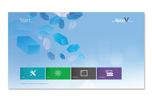 Since I knew that flashrom wouldn’t work on laptops (more on that later), the first thing I tried was to find the flashing tool from the AMI utilities. I didn’t know what kind of BIOS I had, but looking at the screenshot from the Aptio-V page, it was clear that it wasn’t Aptio-V, so I had the choice between AMIBIOS or Aptio-4… so I first tried the one for AMIBIOS, I created a bootable DOS USB stick and copied AFUDOS to it… but it failed, then I tried the tool for Aptio-4, it failed, but it gave me an error message that said I need to use the tool for Aptio-5, so I finally downloaded the AFUDOS utility for the Aptio-V BIOS and that one worked (facepalm!). So I dumped my BIOS, success! Hmm, it’s only a 6MB file, weird…
Now, I figured that “It’s nice and all, but I need to be able to do it from a GNU/Linux platform”, because Librem users will be using PureOS so they’d need a way to dump/flash their BIOS from there. Thankfully, I found that AMI also has a tool called “AFULNX” for GNU/Linux, but for some reason it’s not available for download. I eventually found a link to it, which I can’t seem to find again now, but I also found this great article by Roman Hargrave that explained just how “awesome” (emphasis: sarcasm) AFULNX is. To make a long story short, the AFULNX tool will extract the source for a kernel module and try to build it, which will always fail because they are missing an include, then it deletes those source files, so I’d have to be quick enough to suspend the process before it deletes the files, then make a copy and fix the code so it compiles, then I need that kernel module file to be renamed (otherwise on the next execution it deletes it and retries).
Anyway, I managed to run AFULNX and dump my kernel. It’s another 6MB binary, which is weird because I know from the spec of the chipset, that the flash is supposed to be 8MB. So I compare the BIOS I dumped with the one that was dumped with the Logic Analyzer… Surprise, surprise, they are completely different. After a little investigating, I realize they are not so different, but the BIOS dumped by AFULNX is actually the last 6MB of the flash, while the first 2MB were completely skipped. Comparing the images from the v1 and v2 BIOS images, and also looking at the LA trace, I could see that the first thing being read is the offset 0x10, which contains the magic number 0x5aa5f00f in both images, so I figured that the flash has some sort of “filesystem” which itself contains the BIOS file, and that the AFULNX binary only dumps that BIOS file without the filesystem itself. This meant that my dump was useless in the case of a bricked laptop. I needed a full flash image, otherwise I couldn’t recover.
I then started investigating what this “filesystem” is, and I can’t say that I found a lot of documentation! Thankfully, I know the magic number of 0x5aa5f00f and that helped me find some stuff about it such as a patch on flashrom talking about supporting “ROM layout from IFD“, then, I found the magic number in the ichdesc.py from the tool called romdump which seems to be used to split the raw flash into multiple parts (one of which is the 6MB BIOS file from AFULNX), the file calls it the “ICH flash descriptor”… which led me to something called “ich9gen” that is used to generate that structure (so, is it an ICH9 or an IFD format?). Obviously ICH is a reference to the Intel Controller Hub, which I assume is the one parsing that flash structure (but then why does the coreboot developer manual say that the CPU just loads the top most 16 bytes from the flash? That’s clearly not the case since there is an actual structure to the BIOS and the ICH is the one parsing it prior to the BIOS getting executed). Anyway, I eventually figured out that it’s called (in coreboot speak) a “descriptor” which is used to define “regions” in the flash, one of those regions is the Intel ME firmware, another one is the GbE (Gigabit Ethernet) configuration data, which is used to configure the Intel integrated GbE device (it contains the MAC address for example), as well as the BIOS region which contains the actual UEFI BIOS.
So… at that point I still haven’t managed to do a proper full flash dump using a software method, but at least, I have good BIOS dumps from AFULNX and AFUDOS, right? I then decide to use romdump to extract the BIOS from my logic-analyzer dump, and compare the BIOS dump from AFULNX with the one from the Logic Analyzer, to see what kind of corruption I got from the logic analyzer… and when comparing the two, I realize that the BIOS dumped from AFULNX is the one that is corrupted!

In the AFULNX BIOS dump, there were some huge chunks that were all “0xffffffff” but were filled with data in the logic analyzer BIOS dump. Also, There were some differences in some bytes which, when I looked at the full LA trace, I saw those bytes being read about 20 times with the exact same data being returned each time (confirming the data to be valid) and yet, the one from AFULNX was different…
So I compared the AFULNX dump with the bios dump from AFUDOS, and… the files were different! The two BIOS dumps from AFULNX and AFUDOS were not only very different from the logic analyzer dump, they were also highly different from each other, confirming that they were both corrupted. That just makes everything worse… Why would a software-based dump of the BIOS result in corrupted data? And that’s using the official tool!

If the data is corrupted, how can I trust it? Most importantly how can I write to the BIOS if writing might cause it to be corrupted (i.e.: “is coreboot failing or is the image that was written to the flash wrong”)? Since AFULNX is not open-source, I was hoping to eventually reverse engineer AFULNX itself, to figure out what it does and port those “exceptions” (if there are any) to flashrom to make it support the Librem 13 hardware. That would allow the users to dump and write their flash with the coreboot BIOS using the free/libre and open source flashrom tool, but if that data can’t be trusted, it’s unacceptable. I need to find a way to do a proper and reliable dump of the flash.
Interlude: building coreboot
While I was thinking on how to do the dump, I decided to move to something else: building coreboot for the Librem (I had previously built coreboot for qemu, following the instructions on the wiki, but that’s not very helpful for the Librem 13). So I configured coreboot with ‘make menuconfig’, set the mainboard to the Librem 13, and ran ‘make’. Of course, it failed for some magical reason that I can’t remember right now, but after wrestling a bit with it I eventually realized that I was missing the BLOBs in the 3rdparty/blobs directory, and without it, I couldn’t build it. So I tried to disable the blobs from the config, but it still complained. I couldn’t find information on where to find those blobs that it needed, and I was a bit lost in all of that, to be honest. The only information I found was about the binary situation of coreboot but not on how and where to find the binary blobs, what filename to give to the files, in which directory to put them, etc. I’m going to skip ahead now and spare you the details of long nights crying and wondering “What am I doing wrong?” and just tell you that the coreboot project has a separate repository for binary blobs which needs to be cloned into the ‘3rdparty/’ directory (replacing the empty ‘blobs’ directory in it). Also, even if you ask for a fake IFD in the config, removing the need for the descriptor.bin and me.bin binaries, it will still look for the microcode blobs, which is a separate config option (which was causing things to fail for me).
So, the good news is, the CPU microcode blobs are in that blobs repository… but the descriptor.bin and me.bin binaries are not, and those will have to be created/copied manually; they come from my own flash dump and can be extracted using the tool ‘utils/ifdtool’ from my full raw BIOS dump. Great, I don’t have that!
Back to the dump!
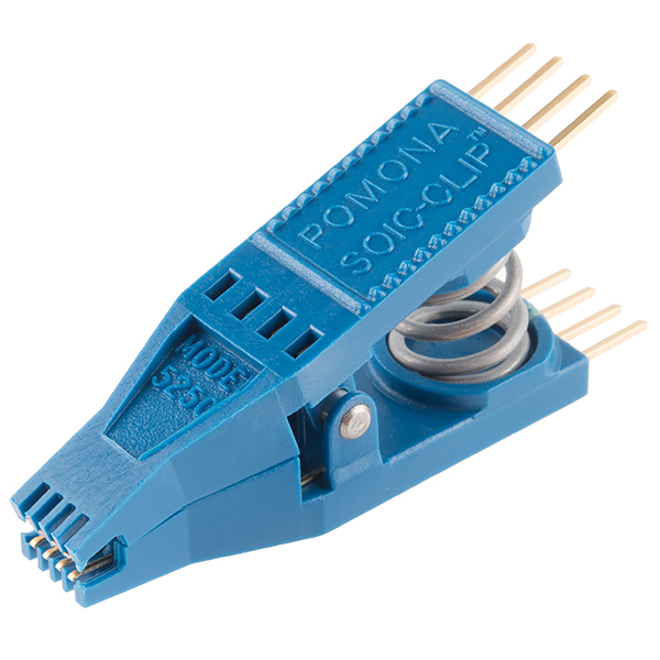
Time to try some alternative methods. In the previous blog post, I spoke about the possibility of using an IC test clip (actually, about using the Logic Analyzer’s test clips) and an external power supply to power the flash chip, but I considered that to be a dangerous thing to do (based on some post I read on the flashrom mailing list). It turns out that while I was afraid of doing that, it’s really not that dangerous and it is actually the preferred method of doing things.
- I apparently got ‘tricked’ into using the socket method simply because I stumbled onto this page in the coreboot wiki and thought that’s what I needed to do.
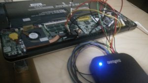
- Last week, Zlatan was at the CCC and participated in the coreboot install session, where he got someone from coreboot to dump his flash, compile coreboot and flash it on his Librem 13. It didn’t work, but it was a helpful event because I realized, “If coreboot developers are using the IC test clip and it’s safe, then I probably also should”, so I researched that further and found posts/wiki pages that confirm it to be a good method to use, then I ordered one, received it overnight, and started playing around with doing a dump of the flash using hardware—but without soldering!
With the IC test clip on hand, I started looking for docs about that tool and saw a lot of wiki pages explaining how to do it. Most of them said to use an ATX Power supply to supply the 3.3V to the chip, and to always connect the power line last. So my first try was to connect the IC clip (so easy to use! Wonderful.) to my breadboard with the same FTDI UM232H as before, then disconnect the battery from the laptop, then connect the power line. The LED on the FTDI suddenly dimmed (it is powering much more than just the flash chip), and my PC was suddenly unable to access the FTDI chip. It still recognizes it but it complains about being unable to reset it. So I brought out a second FTDI chip, and used the first one for all the data/signal lines, and the second one for the power line only (and I did connect the ground from both FTDI chips together), but it was failing, it just couldn’t recognize the flash. I eventually realized that the problem was that flashrom was trying to read from the wrong FTDI (since I had two connected to my PC), so once I specified the right serial number to use, it was still failing, this time with “unable to read serial from device”. I suppose that second FTDI was simply draining my laptop’s USB power or something, I’m not sure exactly what the issue was, but I decided to just go grab myself an ATX power supply and use that instead. After I shorted the PS_ON pin on the power supply to get it to turn on, and made sure the orange wires are for the 3.3V power rail, I connected it all and tried again, it still failed! But at least, I was getting a response. I was getting this response from the chip :
RDID returned 0xe1 0x10 0x0b. RDID byte 0 parity violation. probe_spi_rdid_generic: id1 0xe1, id2 0x100b
But once I checked the datasheet for the MX25L6406E chip, it said that the RDID response (the manufacturer/device ID) should be 0xc2 0x20 0x17, and I noticed that 0xe1 is 1 bit shifted from 0xc2, so I figured that the FTDI must be too fast for the flash chip (even though FTDI was running at 30MHz, and the flash datasheet says it supports a clock of 86MHz—maybe only for reads?). I decided to try lowering the clock, so I changed the clock to 15MHz and it worked! So yay, finally, I was able to dump the flash. I did five dumps, and they all had the exact same checksum, that meant that there was no corruption in any of the dumps. Now I can get back to work!
For the curious, here is the command I used to dump the flash:
../flashrom/flashrom -p ft2232_spi:type=232H,serial=FTVDZ6J5,divisor=4 -c "MX25L6406E/MX25L6408E" -V -r v1.rom
I was then able to use the idftool to split the rom image into the 3 regions it contained (the descriptor, the ME and the BIOS regions). It didn’t contain a GbE region because the Librem does not use the Intel network card. I put the right files in the right directories and coreboot finally compiled!
A good scare
Now, before I test out coreboot, I decided to go grab all the information I can on my hardware, so that if something happens, at least, I would have that. so I went to the Motherboard Porting Guide on coreboot.org, read it, installed all the dependencies, then after quickly looking at the commands that I’m told to copy-paste (just some lspci, lsusb, etc.), I proceeded to paste this block of commands in my terminal in order to gather all the logs that I would need :
 lspci -nnvvvxxxx > lspci.log 2>lspci.err.log
 lsusb -vvv > lsusb.log 2>lsusb.err.log
 superiotool -deV > superiotool.log 2> superiotool.err.log
 inteltool -a > inteltool.log 2> inteltool.err.log
 ectool -i > ectool.log 2>ectool.err.log
 msrtool > msrtool.log 2>msrtool.err.log
 dmidecode > dmidecode.log 2>dmidecode.err.log
 biosdecode > biosdecode.log 2>biosdecode.err.log
 nvramtool -x > nvramtool.log 2>nvramtool.err.log
 dmesg > dmesg.log 2>dmesg.err.log
 flashrom -V -p internal:laptop=force_I_want_a_brick > flashrom_info.log 2>flashrom_info.err.log
 flashrom -V -p internal:laptop=force_I_want_a_brick -r rom.bin > flashrom_read.log 2>flashrom_read.err.log
 acpidump > acpidump.log 2>acpidump.err.log
 for x in /sys/class/sound/card0/hw*; do cat "$x/init_pin_configs" > pin_"$(basename "$x")"; done
 for x in /proc/asound/card0/codec#*; do cat "$x" > "$(basename "$x")"; done
 cat /proc/cpuinfo > cpuinfo.log 2>cpuinfo.err.log
 cat /proc/ioports > ioports.log 2>ioports.err.log
 cat /sys/class/input/input*/id/bustype > input_bustypes.log
And only after I pasted it, I saw the next line in the wiki (below the block of commands) that says, “Save all logs in safe place, and also rom.bin file.”, and noticed that flashrom is used in there too, but since I knew flashrom typically doesn’t work on laptops (as explained in my last blog post) I assumed that command probably just didn’t work and there would be no rom.bin… until I saw the option given to flashrom: laptop=force_i_want_a_brick …

I was half horrified, half amused—this seemed like a ridiculously dangerous thing to put in a long “to be copy/pasted” block of seemingly harmless commands. “Those options shouldn’t be part of a script, they should be set consciously by the user after a big warning!”, I thought. I later discussed this on IRC with the coreboot developers; while most agree that the risk is minimal and it is fairly safe, it was also agreed upon that the option shouldn’t be there in the wiki because of the risk to the user. So that will change soon (if not by a coreboot dev, then I will edit the wiki to add clear warnings).
Thankfully, the resulting “rom.bin” had the full 8MB BIOS dump in my case, and it was all correct (I later compared it with my dump made with the IC clip, and it was almost identical, small differences must be due to the ME constantly writing data to the flash and thus changing some bytes). And so it seems I can indeed dump the flash from software only. Whew!
After some research and discussion on IRC, it turns out that the big problem with flashrom and laptops is the EC (The Embedded Controller), which handles battery charging, the power on/off events,etc..) : if the EC is reading the flash, then you can get some conflicts. Sometimes the EC will appear as a fake flash to the PCH and act as a proxy, but either way, the real problem is just the conflict between EC and PCH trying to access the flash, and it happens to be safe on the Librem 13 because the EC is using a seperate flash chip instead. An old blog post from 2015 on the Purism blog confirms that. So, no more need for AFULNX (or reverse engineering what it does to bypass the EC): we can certainly use flashrom to dump and write the coreboot update to the Librem 13 laptops.
Finding Nemo and Dory: the MRC and the VBIOS
I then used my IC clip setup to write the coreboot image into the flash, and turned on the laptop. The laptop stayed on, but the screen remained black. I asked around on the coreboot IRC channel to get some pointers. After posting my config file, I was told that I am missing 2 important items: the mrc.bin binary blob, and the VBIOS (Video/VGA BIOS); without a VBIOS there would be no graphics support, and without mrc.bin there would be no RAM. So I started searching for this “mrc.bin”, and found very little information on what is “MRC”, what it is for and where I can get it. Thankfully, the folks on IRC were very nice and helped me figure things out.
The MRC blob does the RAM initialization, and it is necessary for the Broadwell architecture to use MRC.bin because there is no native memory init support in coreboot for Haswell/Broadwell chips, unlike older Intel chips. From my understand, it’s in some kind of Google-specific format or that Google is the one creating those mrc.bin binary blobs, and apparently, it can’t be redistributed, but I’m not sure… So I have 3 options, either use the provided MRC.bin from a chromebook’s (with similar chipset) coreboot but not be able to redistribute it (users would have to extract it from the chromebook bios image themselves), or I could use the Intel FSP, but support in coreboot is incomplete, so I’d have to add the support for it somehow, or reverse engineer the memory initialization and re-implement that in coreboot natively. I think reverse engineering it may be the best thing for the future, but for now all I want is to get this running as fast as possible, so I’ll go with the MRC solution for now.
- In any case, I couldn’t just download the mrc.bin file from somewhere, and it was not in coreboot’s blobs repository either. It’s apparently the same blob as the one used in the Google Chromebook Samus which uses a similar Broadwell chipset, all I needed to do was to run the ‘./utils/chromebook/crosfirmware.sh samus’ command which would download the chromebook recovery image for the Samus device, and extract the BIOS from it. Then I could use cbfstool to extract the mrc.bin binary from it as explained in this commit (see additions to the README file). Unfortunately, cbfstool would refuse to extract/print the BIOS because it couldn’t detect it as being a coreboot BIOS. Thankfully, someone on IRC (coolstar) quickly told me to use ‘-r BOOT_STUB’ option which fixes things. Once I did that, I got the mrc.bin file.
- Then I was told I would also need the refcode… “What is the refcode?” Well, they didn’t know, and it doesn’t seem to be clear either from the coreboot config help page, as it only says it’s an “external reference code to be put in cbfs” (by the way, cbfs is the coreboot filesystem which contains all the coreboot code and blobs, etc..). Eventually, I found some email on the U-boot mailing list saying that the Broadwell chipsets need an additional reference code to be executed in order to initialize the PCH. So I extracted the refcode binary blob as well and added it to coreboot.
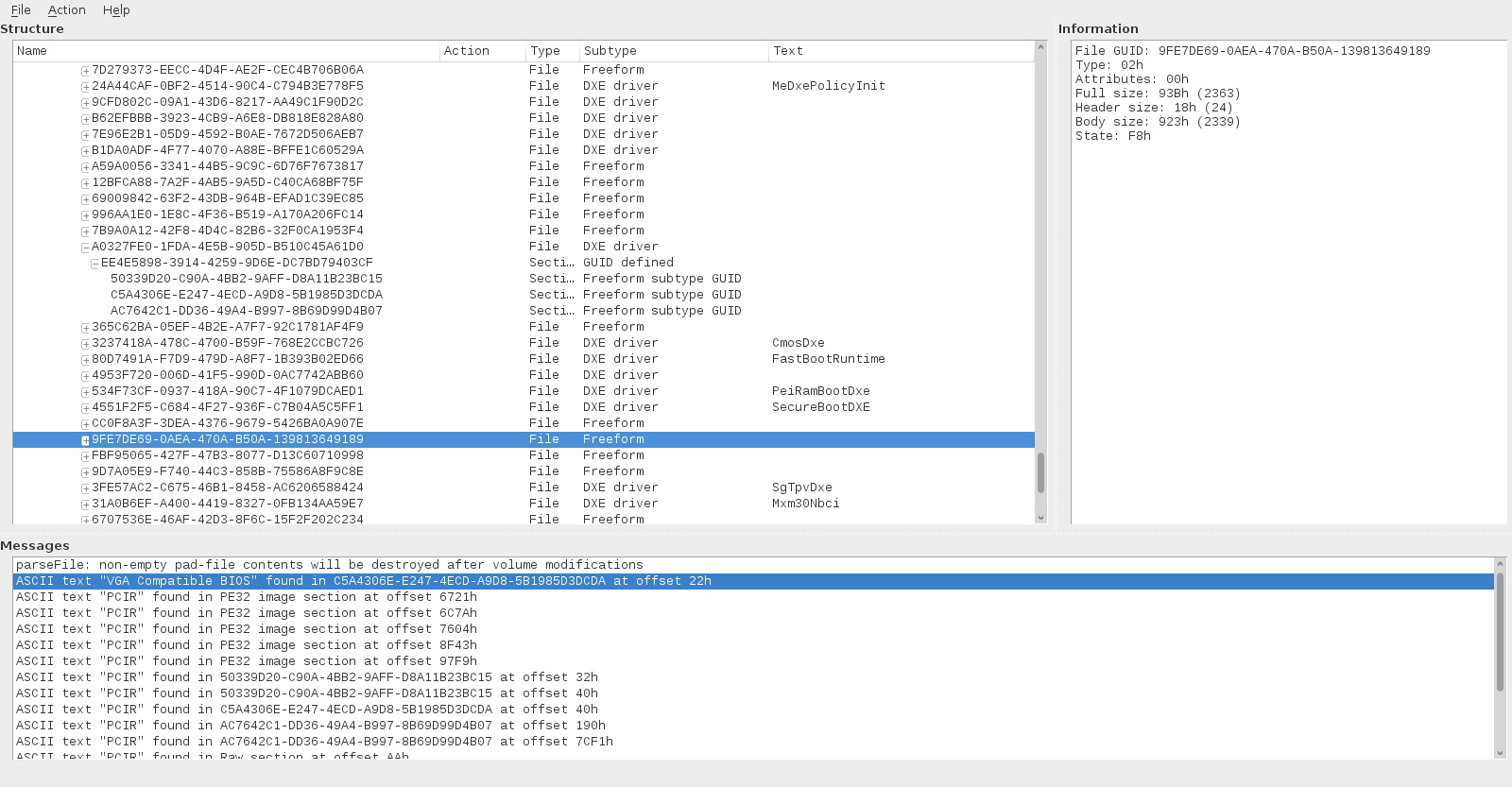
The VBIOS, on the other hand, was the easy part. I followed the instructions from the coreboot wiki, I tried the bios_extract method, but it couldn’t recognize my BIOS as being an AMI BIOS, so I looked in the bios_extract source code, and figured out how it detects the BIOS vendor (it looks for specific strings in it), and I realized that my BIOS didn’t fit (it didn’t have anything close to those strings at all) and it wasn’t a simple bug to fix it and make it work… so I figured, maybe it’s considered a “UEFI” bios, so I followed the “UEFI method” which uses the UEFITool, so I installed it, ran it, gave it my vendor BIOS, and it recognized it as a UEFI bios and showed me a tree of “lots of stuff”:
To find the VBIOS, the wiki says to:
* Look for the “CSMCORE” DXE Driver ? usually having the hash ‘a062cf1f-8473-4aa3-8793-600bc4ffe9a8’?
* Search for text “VGA Compatible BIOS” (uncheck unicode)
* Search for text “PCIR” (uncheck unicode)
And so, I did, I found the DXE Driver called “CSM DXE” with the correct hash. I thought that I would then open that item and search for “VGA Compatible BIOS” in it, but nope, when I did the search, it gave me a completely different module, and when I searched for “PCIR” it gave me a bunch of different modules which matched… and I had no idea what to chose. I made my choice on the single result from “VGA Compatible BIOS” and extracted that one. I tried it and it didn’t work, so I wasn’t sure if it was right, but it felt right. Eventually, I put back my original vendor BIOS on the flash, booted the Librem 13 into PureOs, and used the “extraction from mapped memory” method to grab the VBIOS directly from GNU/Linux. As I compared it, it was identical to the vbios.bin that I extracted from UEFITool, so I at least knew that I had the right file.
Next steps
 I now have coreboot with the proper descriptor, ME regions, VBIOS, MRC.bin (and refcode), but I don’t know yet why it still doesn’t boot. The next step for me will be to see how I can debug it. There are some ways to debug coreboot but I haven’t looked at them yet. There’s an old blog post about debugging coreboot on the Librem 13, but I’m not sure I’m in the mood to be soldering on the LPC lines (and where are they?), but Zlatan in the CCC coreboot session said that the coreboot developer was able to debug that it had stopped at the vga init stage for him (they didn’t have the VBIOS, I think), so there is obviously going to be a way to do that, and I doubt they soldered on the LPC lines in the middle of a conference. I think it’s safe to assume that I could use a beaglebone black (which I have already) and use the EHCI debug port to capture debug information. That will be my challenge for next week and once I achieve that, I will be able to debug what happens and hopefully figure out what went wrong and fix coreboot so it can boot the Librem 13!
Now, there are still some questions that I needed to know.
- For example, assuming I get coreboot to work on my Librem 13, how can I know that it’s doing it’s job? I need a checklist of what coreboot is supposed to be doing and a way to check if it does it correctly. Thankfully, I found this old article that lists a checklist of 32 items for the Librem 13 coreboot port to be considered done.
- I also wanted to know what are the risks to the motherboard if I have a wrong configuration in coreboot, are there components that could get fried? I got the answer today from IRC (thank you agra, avph, felix_, icon, for all the help), and the answer is that it’s “highly unlikely” that I could damage the board, although it is possible, such as supplying a too high voltage to the memory controller. Most boards are safe however, as the voltage regulator would not allow such things, but some motherboards might not be as safe as others, so I’d need to check the voltage regulators on my board to see what kind of values they allow.
So, now, I feel much more at ease with everything. My knowledge is of course still quite incomplete, but I don’t feel as blind as I felt last month, and I have a clear path towards what I need to be doing. Hopefully, I can find out easily how to enable debugging next week, figure out where everything went wrong, fix it, and “Tada! coreboot works!” But yeah, it’s probably going to be a little more complicated than that 😉
Recent Posts
Related Content
- Code is Power!
- PureBoot Not Vulnerable to UEFI Exploits (Again)
- Intel AX200 Wi-Fi/Bluetooth Shipping for New Orders
- Librem 11 Memory Adventures
- PureBoot Framebuffer Boot Support